
The ESP8266 module is a versatile Wi-Fi module that can be easily programmed using the Arduino UNO board. This tutorial aims to provide a step-by-step guide for beginners to get started with programming the ESP8266 module using Arduino UNO, enabling you to build exciting IoT projects.
Let’s get started.
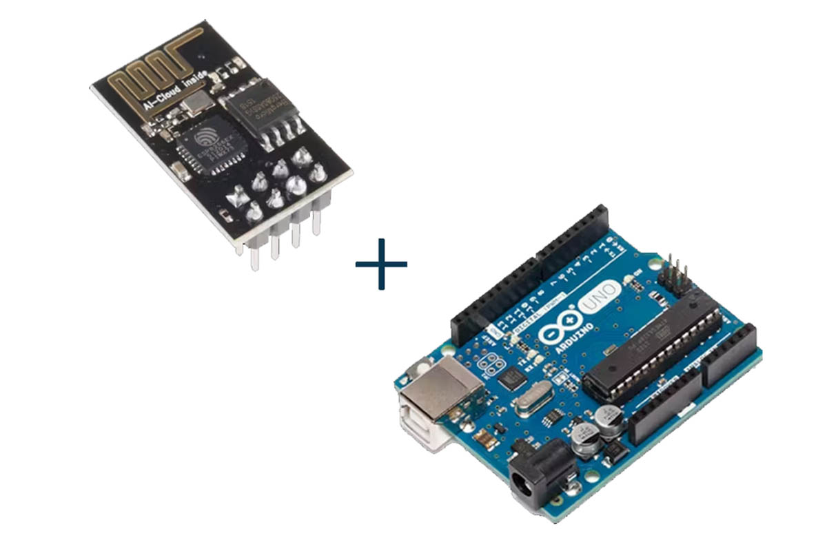
Step 1: Gather the Necessary Components
Before starting, ensure you have the following components:
- Arduino UNO board
- ESP8266 module
- USB cable for Arduino UNO
- Breadboard and jumper wires
- USB cable for ESP8266 module (if required)
Step 2: Set Up Arduino IDE
If you haven’t already, download and install the Arduino IDE from the official website. Open the Arduino IDE, then navigate to File > Preferences. In the “Additional Boards Manager URLs” field, add the following URL:
http://arduino.esp8266.com/stable/package_esp8266com_index.json
Step 3: Install the ESP8266 Board Package
Navigate to Tools > Board > Boards Manager. In the search bar, type “ESP8266” and install the “esp8266” by ESP8266 Community package. Once installed, select your ESP8266 board from Tools > Board. Choose the appropriate board variant based on your ESP8266 module.
Step 4: Wire ESP8266 with Arduino UNO
Connect the ESP8266 module to the Arduino UNO as follows:
- ESP8266 VCC to Arduino 3.3V
- ESP8266 GND to Arduino GND
- ESP8266 RX to Arduino pin 2 (TX)
- ESP8266 TX to Arduino pin 3 (RX)
- ESP8266 CH_PD to Arduino 3.3V
- ESP8266 GPIO0 to Arduino GND (for programming mode)
Step 5: Upload Blink Sketch to ESP8266
Now, let’s upload a simple “Blink” sketch to the ESP8266 module to test the setup. Open the Arduino IDE and select File > Examples > ESP8266 > Blink. Before uploading, ensure you’ve selected the correct board and port from the Tools menu.
Click the upload button (right arrow icon) to upload the sketch to the ESP8266 module.
Step 6: Verify Upload and Test
Once the upload is complete, disconnect GPIO0 from GND, then reset the ESP8266 module. You should see the onboard LED (connected to GPIO2) blinking at a regular interval, indicating a successful upload.
Step 7: Write Your First ESP8266 Program
Now that you’ve successfully uploaded a sketch, it’s time to write your own program. Here’s a simple example that connects the ESP8266 to a Wi-Fi network and prints the IP address to the serial monitor:
#include <ESP8266WiFi.h>
const char* ssid = “YOUR_SSID”;
const char* password = “YOUR_PASSWORD”;
void setup() {
Serial.begin(9600);
delay(10);
Serial.println();
Serial.println(“Connecting to Wi-Fi…”);
WiFi.begin(ssid, password);
while (WiFi.status() != WL_CONNECTED) {
delay(500);
Serial.print(“.”);
}
Serial.println(“”);
Serial.println(“Wi-Fi connected”);
Serial.println(“IP address: “);
Serial.println(WiFi.localIP());
}
void loop() {
// Your code here
}
Replace YOUR_SSID and YOUR_PASSWORD with your Wi-Fi network credentials. Upload the sketch to the ESP8266 module and open the serial monitor (Tools > Serial Monitor) to view the IP address once the ESP8266 connects to the Wi-Fi network.
Step 8: Expand Your Project
With the basics covered, you can now start building more complex projects using the ESP8266 module and Arduino UNO.
Explore various sensors, actuators, and communication protocols to create innovative IoT applications.
Conclusion
In this tutorial, you’ve learned how to program the ESP8266 module using the Arduino UNO board. With the ability to connect to Wi-Fi networks and interact with sensors, the ESP8266 opens up endless possibilities for IoT projects.
Keep experimenting and have fun exploring the world of embedded systems and IoT!